Selasa, 03 Juni 2008
AlhamduLiLLah....
Minggu, 01 Juni 2008
Finally

yeah.....Finally.....Omron itu....finally orang emerson pada care juga dan saya rasa dari baca - baca e-mail, Omron Tumbang Koling Itu dah bukan tanggung jawab saya untuk ngantar ke site. Bagaimana gak seneng hati ini,Untuk nganter Omron itu ke site butuh dana tak kurang 1 Jeti bo....(pengalaman ngantar modul kemaren). Tapi saya kok jadi berfikir....mungkin saya ngantar modul kemaren terlalu bodoh ya...soalnya kan itu bukan lagi tanggung jawab saya sebagai installer? tapi biarlah uang 1 Jeti itu melayang...(duh...mau nyari segitu sampai jungkir balik dibuang begitu saja)...
Kamis, 29 Mei 2008
Sebenarnya

Sebenernya Esia Proyek Samarinda telah ditandatangani oleh yang namanya bapak yusuf, namun ap boleh dikata....BAST nya belum ditandatangani...saya minta tandatangan sama yang namanya Pak Nofri...sulitnya minta ampun ....apa mau di jabel saja rectifier ini?
Rabu, 28 Mei 2008
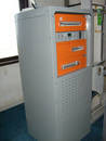
Rectifier Tumbang Koling

Di samping dua modul site Bumi Hutan Lestari (Tumbang Koling) rusak, relay omron satu buah juga mengalami kerusakan. Bukan mau menghakimi tetapi saya mau menunjukkan fakta - fakta dari foto yang berhasil saya ambil. dari foto tersebut coba anda lihat jarak antara bagian atas modul kontrol dengan elemen rack di atasnya, kemudian anda teruskan ke kanan melihat jarak antara bagian atas modul rectifier 1 dan elemen rak di atasnya, terlihat semakin longgar bukan?. Hal ini disebabkan rak tersebut melengkung.
Penyebab rack melengkung bisa bermacam - macam, mungkin karena dari pabrik sudah begitu, mungkin karena pengepakan di gudang emerson , mungkin karena permasalahan loading / unloading tracking yang kurang hati - hati, mungkin karena unpack yang kurang hati hati dan sebagainya.
Hal yang saya lihat disini dan bisa kita lakukan perubahan yaitu masalah pengiriman modul yang di tancapkan di kabinet. Karena bisa saja hal inilah yang menyebabkan melengkungnya kabinet tersebut. Untuk medan yang tidak berat mungkin hal ini tidak bermasalah, tetapi medan daerah Tumbang Koling, Cempaga Hulu merupakan medan yang cukup berat bisa anda lihat di foto - foto beratnya (baca:asyiknya) medan tumbang koling . saya sendiri tidak berani memacu mobil melebihi 30 km /jam.
Selasa, 27 Mei 2008
Another Story Of Tumbang Koling
Di Dalam sana ada banyak perusahaan kelapa sawit salah satunya yaitu Bumi Hutan Lestari, Wana Asri Fajarindo Dll.
Daerah Ini Adalah pertengahan antara Palangkaraya dan Sampit. Jadi Kalau mau charter mobil dari kedua Kota Tersebut. Untuk Menuju Daerah Tumbang Koling Kita Harus Berangkat Pagi - Pagi Bener. Kalau Tidah Maka Nanti Kita akan kemalaman. Kalau kemalaman dikit sudah ada preman-preman kampung.
Senin, 26 Mei 2008
Rectifier
A rectifier is an electrical device that converts alternating current to rectified direct current, a process known as rectification. Rectifiers are used as components of power supplies and as detectors of radio signals. Rectifiers may be made of solid state diodes, vacuum tube diodes, mercury arc valves, and other components.
A circuit which performs the opposite function (converting DC to AC) is known as an inverter.
When only one diode is used to rectify AC (by blocking the negative or positive portion of the waveform), the difference between the term diode and the term rectifier is merely one of usage, i.e., the term rectifier describes a diode that is being used to convert AC to DC. Almost all rectifiers comprise a number of diodes in a specific arrangement for more efficiently converting AC to DC than is possible with only one diode. Before the development of silicon semiconductor rectifiers, vacuum tube diodes and copper(I) oxide or selenium rectifier stacks were used.
Early radio receivers, called crystal radios, used a "cat's whisker" of fine wire pressing on a crystal of galena (lead sulfide) to serve as a point-contact rectifier or "crystal detector". In gas heating systems flame rectification can be used to detect a flame. Two metal electrodes in the outer layer of the flame provide a current path and rectification of an applied alternating voltage, but only while the flame is present.
Half-wave rectification
In half wave rectification, either the positive or negative half of the AC wave is passed, while the other half is blocked. Because only one half of the input waveform reaches the output, it is very inefficient if used for power transfer. Half-wave rectification can be achieved with a single diode in a one phase supply, or with three diodes in a three-phase supply.

A full-wave rectifier converts the whole of the input waveform to one of constant polarity (positive or negative) at its output. Full-wave rectification converts both polarities of the input waveform to DC (direct current), and is more efficient. However, in a circuit with a non-center tapped transformer, four diodes are required instead of the one needed for half-wave rectification. (See semiconductors, diode). Four rectifiers arranged this way are called a diode bridge or bridge rectifier:

For single-phase AC, if the transformer is center-tapped, then two diodes back-to-back (i.e. anodes-to-anode or cathode-to-cathode) form a full-wave rectifier (in this case, the voltage is half of that for the non-tapped bridge circuit above, and the diagram voltages are not to scale).


A very common vacuum tube rectifier configuration contained one cathode and twin anodes inside a single envelope; in this way, the two diodes required only one vacuum tube. The 5U4 and 5Y3 were popular examples of this configuration.

For three-phase AC, six diodes are used. Typically there are three pairs of diodes, each pair, though, is not the same kind of double diode that would be used for a full wave single-phase rectifier. Instead the pairs are in series (anode to cathode). Typically, commercially available double diodes have four terminals so the user can configure them as single-phase split supply use, for half a bridge, or for three-phase use.

Most devices that generate alternating current (such devices are called alternators) generate three-phase AC. For example, an automobile alternator has six diodes inside it to function as a full-wave rectifier for battery charging applications.
Peak loss
An aspect of most rectification is a loss from peak input voltage to the peak output voltage, caused by the built-in voltage of the diodes (around 0.7 V for ordinary silicon p-n-junction diodes and 0.3 V for Schottky diodes). Half-wave rectification and full-wave rectification using two separate secondaries will have a peak voltage loss of one diode drop. Bridge rectification will have a loss of two diode drops. This may represent significant power loss in very low voltage supplies. In addition, the diodes will not conduct below this voltage, so the circuit is only passing current through for a portion of each half-cycle, causing short segments of zero voltage to appear between each "hump".
Rectifier output smoothing
While half-wave and full-wave rectification suffice to deliver a form of DC output, neither produces constant-voltage DC. In order to produce steady DC from a rectified AC supply, a smoothing circuit, sometimes called a filter[1], is required. In its simplest form this can be what is known as a reservoir capacitor, Filter capacitor or smoothing capacitor, placed at the DC output of the rectifier. There will still remain an amount of AC ripple voltage where the voltage is not completely smoothed.
Sizing of the capacitor represents a tradeoff. For a given load, a larger capacitor will reduce ripple but will cost more and will create higher peak currents in the transformer secondary and in the supply feeding it. In extreme cases where many rectifiers are loaded onto a power distribution circuit, it may prove difficult for the power distribution authority to maintain a correctly shaped sinusoidal voltage curve.
For a given tolerable ripple the required capacitor size is proportional to the load current and inversely proportional to the supply frequency and the number of output peaks of the rectifier per input cycle. The load current and the supply frequency are generally outside the control of the designer of the rectifier system but the number of peaks per input cycle can be affected by the choice of rectifier design.
A half-wave rectifier will only give one peak per cycle and for this and other reasons is only used in very small power supplies. A full wave rectifier achieves two peaks per cycle and this is the best that can be done with single-phase input. For three-phase inputs a three-phase bridge will give six peaks per cycle and even higher numbers of peaks can be achieved by using transformer networks placed before the rectifier to convert to a higher phase order.
To further reduce this ripple, a capacitor-input filter can be used. This complements the reservoir capacitor with a choke and a second filter capacitor, so that a steadier DC output can be obtained across the terminals of the filter capacitor. The choke presents a high impedance to the ripple current.[2]
If the DC load is very demanding of a smooth supply voltage, a voltage regulator will be used either instead of or in addition to the capacitor-input filter, both to remove the last of the ripple and to deal with variations in supply and load characteristics.
Voltage-doubling rectifiers
The simple half wave Rectifier can be built in two versions with the diode pointing in opposite directions, one version connects the negative terminal of the output direct to the AC supply and the other connects the positive terminal of the output direct to the AC supply.By combining both of these with separate output smoothing it is possible to get an output voltage of nearly double the peak AC input voltage. This also provides a tap in the middle which allows use of such a circuit as a split rail supply.
A variant of this is to use two capacitors in series for the output smoothing on a bridge rectifier then place a switch between the midpoint of those capacitors and one of the AC input terminals. With the switch open this circuit will act like a normal bridge rectifier with it closed it will act like a voltage doubling rectifier. In other words this makes it easy to derive a voltage of roughly 320V (+/- around 15%) DC from any mains supply in the world, this can then be fed into a relatively simple switched mode power supply.
Cascaded stages of diodes and capacitors can be added to make a voltage multiplier. These circuits can provide a potential several times that of the peak value of the input AC, although limited in current output and regulation. Voltage multipliers are used to provide the high voltage for a CRT in a television receiver, or for powering high-voltage tubes such as image intensifiers or photomultipliers.
Applications
The primary application of rectifiers is to derive DC power from an AC supply. Virtually all electronics except simple motor circuits such as fans require a DC supply but mains power is AC so rectifiers find uses inside the power supplies of virtually all electronic equipment.
Converting DC voltage from one level to another is much more complicated. One method of such DC-to-DC conversion is to first convert to AC (using a device called an inverter), then use a transformer to change the voltage, and finally rectify it back to DC.
Rectifiers also find a use in detection of amplitude modulated radio signals. The signal may or may not be amplified before detection but if unamplified a very low voltage drop diode must be used. When using a rectifier for demodulation the capacitor and load resistance must be carefully matched. Too low a capacitance will result in the high frequency carrier passing to the output and too high will result in the capacitor just charging and staying charged.

Rectifiers are also used to supply polarised voltage for welding. In such circuits control of the output current is required and this is sometimes achieved by replacing some of the diodes in bridge rectifier with thyristors, whose voltage output can be regulated by means of phase fired controllers.
Rectification technologies
Electromechanical
Early power conversion systems tended to be purely mechanical in design. This was initially due to the lack of scientific knowledge, since at the time electric power was still a new field of research.
Mechanical rectification systems usually rely on some form of rotation or resonant vibration in order to move quickly enough to match the frequency of the input power source, and cannot operate beyond several thousand cycles.
Due to the complexity of mechanical systems, they have traditionally needed a high level of maintenance to keep operating correctly. Moving parts will have friction, which requires lubrication and replacement due to wear. Opening mechanical contacts under load results in electrical arcs and sparks that heat and erode the contacts.
Synchronous Rectifier
To convert AC currents into DC current in electric locomotives, a synchronous rectifier may be used. It consists of a synchronous motor driving a set of heavy-duty electrical contacts. The motor spins in time with the AC frequency and periodically reverses the connections to the load just when the sinusoidal current goes through a zero-crossing. The contacts do not have to switch a large current, but they need to be able to carry a large current to supply the locomotive's DC traction motors.
Vibrator
In the past, the vibrators used in battery-to-high-voltage-DC power supplies often contained a second set of contacts that performed synchronous mechanical rectification of the stepped-up voltage.
Motor-Generator Set
Another type of rectifier, a motor-generator set or the similar rotary converter, is not a rectifier in the strict sense. Here, an AC motor is mechanically coupled to a DC generator. The DC generator produces a multiphase alternating current in its windings, but a commutator is used to convert the alternating currents into a direct current output; or a homopolar generator directly produces direct current without need for a commutator. Such devices are useful for producing thousands of amperes of direct current at tens to hundreds of volts.
The electrolytic rectifier [3] was an early device from the 1900s that is now no longer used. When two different metals are suspended in an electrolyte solution, it can be found that direct current flowing one way through the metals has less resistance than the other direction. These most commonly used an aluminum anode, and a lead or steel cathode, suspended in a solution of ammonia phosphate.
The rectification action is due to a thin coating of aluminum hydroxide on the aluminum electrode, formed by first applying a strong current to the cell to build up the coating. The rectification process is temperature sensitive, and for best efficiency should not operate above 86 degrees F. There is also a breakdown voltage where the coating is penetrated and the cell is short-circuited. Electrochemical methods are often more fragile than mechanical methods, and can be sensitive to usage variations which can drastically change or completely disrupt the rectification processes.
Mercury Arc
Another type of rectifier used in high-voltage direct current power transmission systems and industrial processing between about 1909 to 1975 is a mercury arc rectifier or mercury arc valve. The device is enclosed in a bulbous glass vessel or large metal tub. One electrode, the cathode, is submerged in a pool of liquid mercury at the bottom of the vessel and one or more high purity graphite electrodes, called anodes, are suspended above the pool. There may be several auxiliary electrodes to aid in starting and maintaining the arc. When an electric arc is established between the cathode pool and suspended anodes, a stream of electrons flows from the cathode to the anodes through the ionized mercury, but not the other way.
These devices can be used at power levels of hundreds of kilowatts, and may be built to handle one to six phases of AC current. Mercury arc rectifiers have largely been replaced by silicon semiconductor rectifiers from the mid 1970s onward. The most powerful mercury arc rectifiers ever built were installed in the Manitoba Hydro Nelson River Bipole HVDC project, with a combined rating of more than one million kilowatts and 450,000 volts.
Argon Gas Electron Tube
The General Electric Tungar rectifier was an argon gas-filled electron tube device with a tungsten filament cathode and a carbon button anode. It was useful for battery chargers and similar applications from the 1920s until low-cost solid state rectifiers supplanted it. These were made up to a few hundred volts and a few amperes rating, and in some sizes strongly resembled an incandescent lamp with an additional electrode.
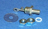
Selenium and copper oxide rectifiers
Once common until replaced by more compact and less costly silicon solid state rectifiers, these units used stacks of metal plates and took advantage of the semiconductor properties of selenium or copper oxide. [4] While selenium rectifiers were lighter in weight and used less power than comparable vacuum tube rectifiers, they had the disadvantage of finite life expectancy, increasing resistance with age, and were only suitable to use at low frequencies. Both selenium and copper oxide rectifiers have somewhat better tolerance of momentary voltage transients than silicon rectifiers.
Typically these rectifiers were made up of stacks of metal plates or washers, held together by a central bolt, with the number of stacks determined by voltage; each cell was rated for about 20 volts. An automotive battery charger rectifier might have only one cell; the high-voltage power supply for a vacuum tube might have dozens of stacked plates. Current density in an air-cooled selenium stack was about 600 mA per square inch of active area (about 90 mA per square centimeter).
Metal-Oxide Semiconductor, Field-Effect Transistor
In recent years semiconductor synchronous rectifiers have been designed; using MOSFET transistors, they can also rectify with a very low forward voltage drop and have the additional advantage of being able to switch at extremely high speeds. Semiconductor synchronous rectifiers are now widely used in those electronic power supply units designed for very low output voltages (where the voltage drop in an ordinary rectifier would represent an unacceptable fraction of the total output voltage).
Jumat, 23 Mei 2008
Barang Yang Kesasar Itu....
 Inilah Barang Yang Kesasar Itu...(Klik UntukMemperbesar) Sejatinya memang barang ini di kirim untukIndosat...tapi berhubung gak cocok ama permintaan maka dikirim ke Tumbang Koling...karena kebetulan site Tumbang Koling ada yang rusak mmodulnya...
Dokument Terkait : Foto Barang Tersebut...
Senin, 19 Mei 2008
Installasi Esia Samarinda
Esia Samarinda Terletak Di Jl. Awang Long Di Belakang Hotel Mesra. GUa dah dua kali install ini site. Kali Ini Gua SWAP Rectfier. Installasinya Sendiri Gak Begitu susah...hanya ATP nya Pak.....susah amat....kenapa seeh...takut ditagih? belum punya uang untuk mbayar emerson? atau mau nyari utangan dulu untuk mbayar?
Dokumen Terkait :Foto Esia Samarinda (Flickr)
Photo Esia Samarinda (shareapic.net)
Installasi Site Bengkuring
Dokumen Terkait : Foto Installasi Bengkuring (Shareapic.net)
Installasi Site BumiHutan Lestari (Tumbang Koling)
 Installasi Site Ini aku kerjakan sesudah selesai installasi daripada site Kuala Jelai...sekalian perjalanan pulang....Site Tumbang Koling ini gak beda jauh dengan Kuala Jelai....medanya susah....tapi bagi gua sih sengsara yang membawa nikmat...Tumbang Koling adalah Daerah perkebunana Kelapa Sawit, makanya sempat bingung orang orang dengan nama site ini...kalau aku sih suka nyebut nama desanya saja....sebetulnya nama site nya site BHL (Bumi Hutan Lestari) ---> nama sebuah perusahaan sawit, Dari Banjar seperti biasa aku naik kendaraan favoritku xenia plat Jakarta (yang gak pernah ketangkep he he he...) Melalui Kota Palangkaraya (ngadem sebentar makan minum) sekitar setengah jam perjalanan aku liak di papan papan nama kantor pemerintahan sudah menunjukkan sampai pada kecamatan Cempaga Hulu, Aku turun dari xenia dan nanya sana nanya situ akhirnya aku sampai di pintu masuk perkebunan...ngobrol bentar sama penjada portal, dia bilangnya sekitar 50 Km lagi sampai...kalau ngojek ya sekitar 15o ribuan...katanya. tapi aman kan pak....oh..aman dhik...dijamin....(gua takut soalnya sendirian..he..he..). Masuk Ke Perkebunan, penasaran juga gua akhirnya gua enolin spedometer....di dalam ternyata banyak perusahaan perkebunan Gak Hanya BHL...ada Wana Asri Fajarindo....pokoknya aku tarik lurus terus sesuai petunjuk tukang portal...By the Way...indah juga pemandangan menuju perkebunan...sekali sekali nampak orang naik motor (orang perkebunan) dan selama perjalanan ke dalam saya hanya di salip ama truk truk kelapa sawit dan 3 mobil pribadi...(di salip mulu karena aku jalan pelan banget) gak berani deh laju laju soalnya jalannya jelek banget....aku aja sangsi gardannya kena enggak...apalagi kalau melewati jalanan yang seperti diukir..(Lihat Gambarnya di sini)...wah....seakan akan mobil mau rontok semua....
Dokumen Terkait : Eksotime Perjalanan ke Site Tumbang Koling (Shareapic.net)
Foto Installasi Site Tumbang Koling (Shareapic.net)